Background
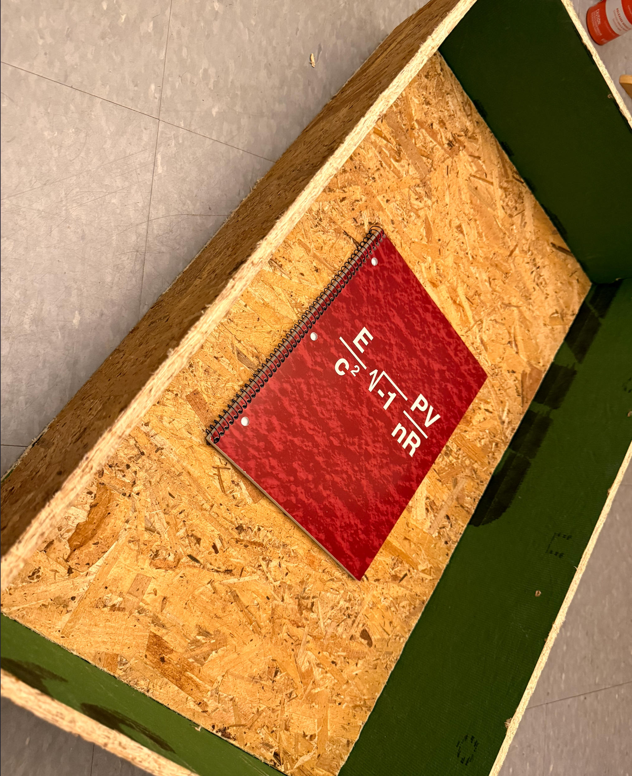
The manga, and later the anime adaptation Death Note, was one of my all-time favorites. There were so many strategies, wit, and clever tricks in it that really impressed me when I was little. Among all the amazing plot points, one design that I still remember to this day is the drawer with the hidden compartment scene, in which the main protagonist, Light Yagami, concealed his dangerous Death Note.
Fortunately—or unfortunately—in the original manga, there's already a very detailed depiction of how to make such a drawer. The mechanism was elegant and efficient: anyone who didn't know how to open the drawer properly would complete the circuit hidden beneath it, which would ignite the inflammable chemical placed around the notebook and set it on fire.
Obviously, I don't want to put my stuff, desk, or dorm room at risk of being burned down. Most of the things I want to hide have sentimental value, not because they're illegal. More importantly, I don't want Neil to think he's teaching or imparting knowledge that could be used by an arsonist in the future. So, I decided to alter the mechanism a little bit.
Proposed Adjustments
I'm getting rid of the fire-igniting feature with chemicals and replace it with a completely benign alert system that notifies me if someone is trying to open the drawer without authorization. I used nano banana to help me draw the basic idea.
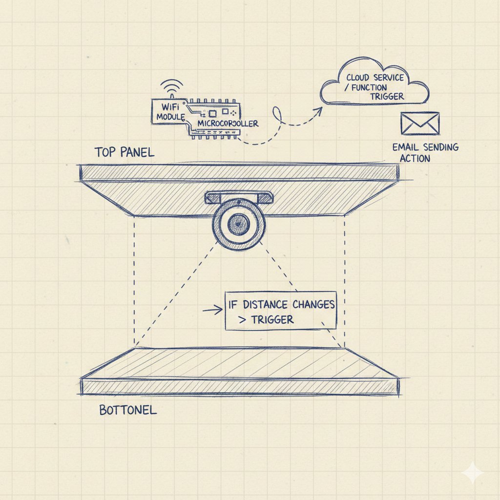
Intuitively, many would argue that an "alert" system could be entirely achieved by simply installing a camera in the room. While this may be true, I believe many share the experience of spotting something off about a friend and choosing not to bring it up, to avoid awkwardness. This is similar. By implementing a subtle, less noticeable approach, I spare both the culprit and myself from that discomfort.
Also, even though it is an incredibly simple device, it is the culmination of this semester's study. I had the skills needed summarized below.
Knowledge and Skills Needed
Fusion · Parametric Design
Fusion / Prusa Slicer · 3D Printing
CNC Milling Machine · Making Something Big
Arduino · Input / Electronic Design
Output / Networking & Communication
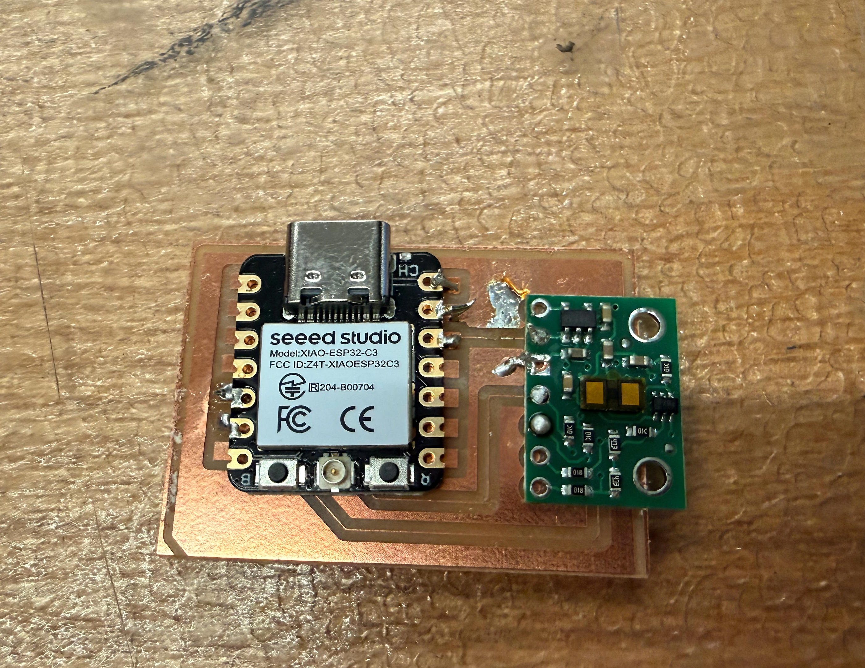
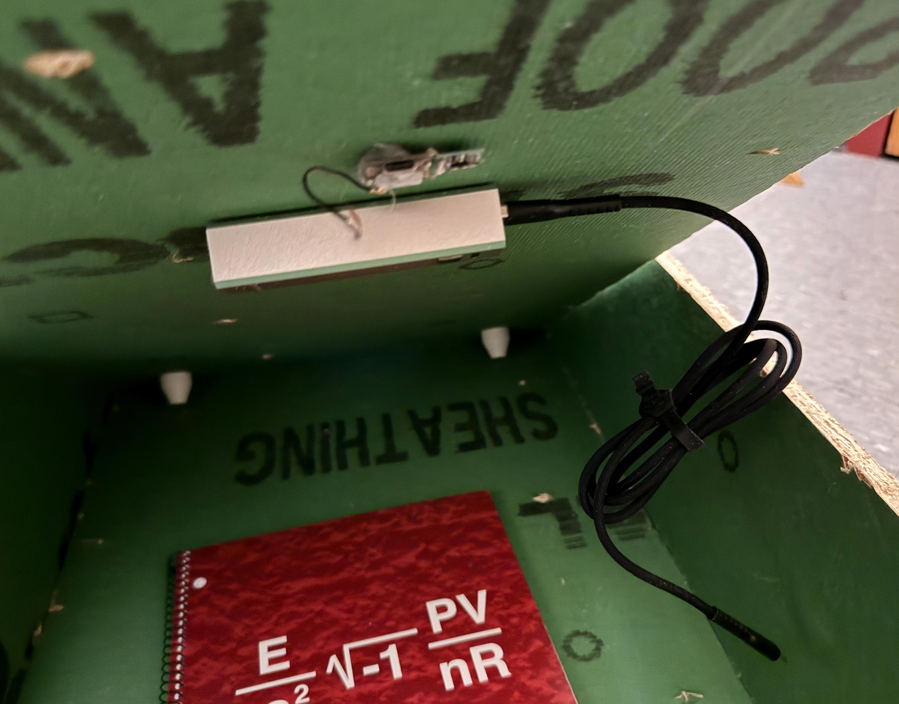
In the past weeks, I have gradually prepared the parts needed for this project. At this moment I have:
To make the system more integrated and just generally better looking, I also designed a case that would protect the board and chip.
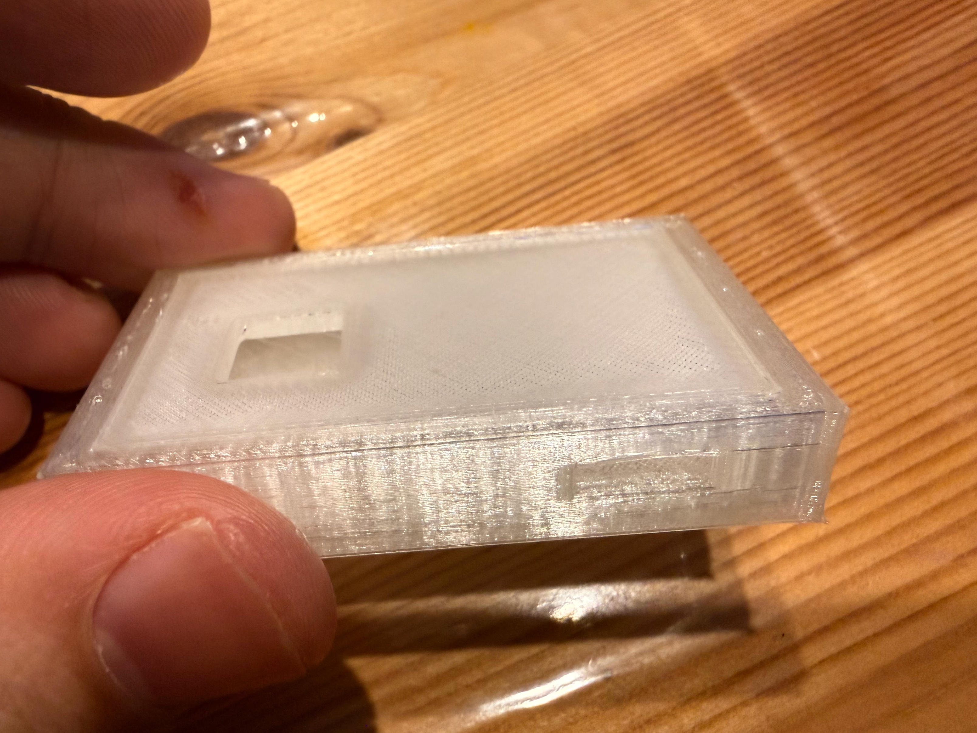
Despite my best effort to make it as accurate as possible, the cut out for USB-C cable seems to be too small to fit the USB port
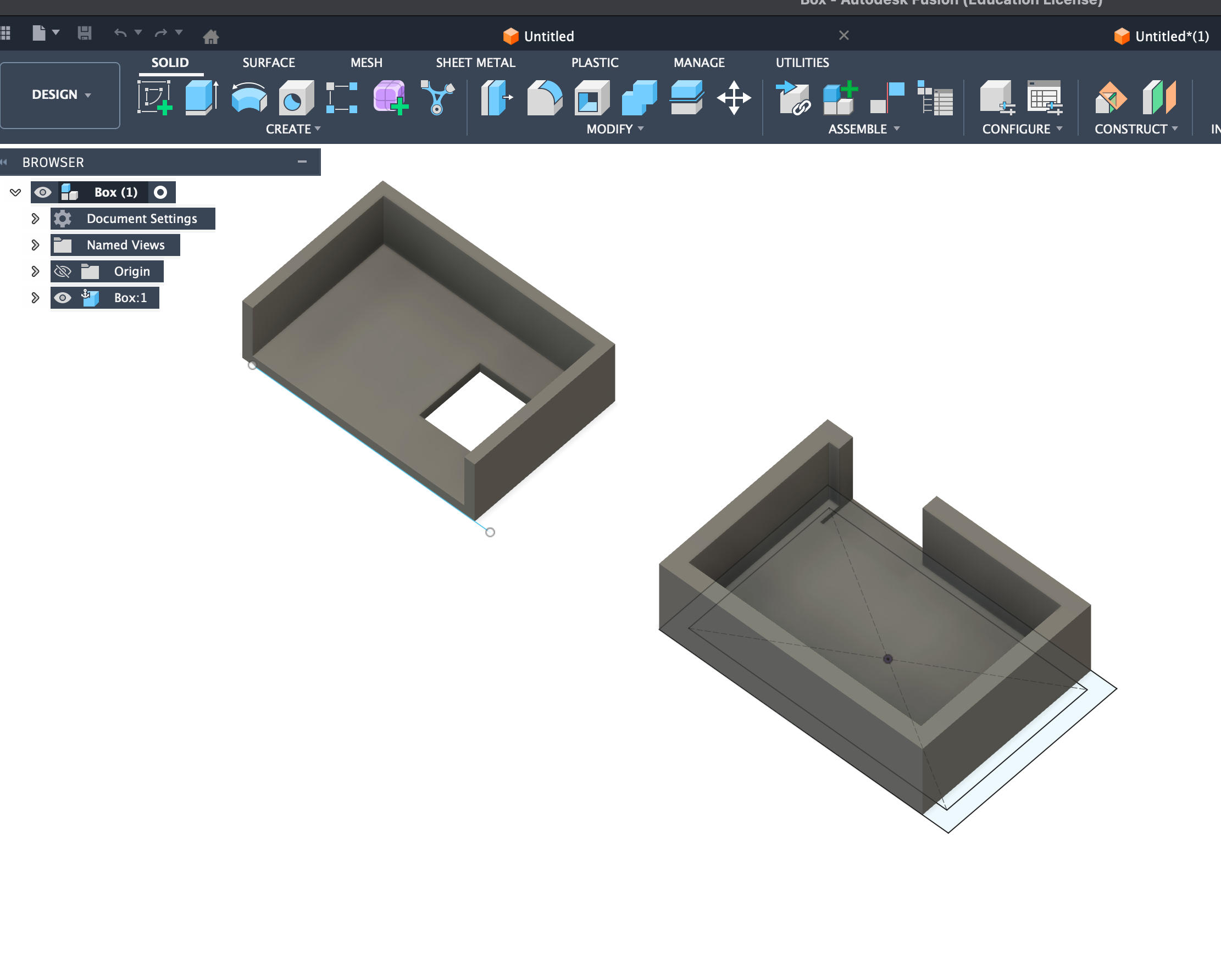
Made the cutout more forgiving

I selected TPU filament for its soft feature
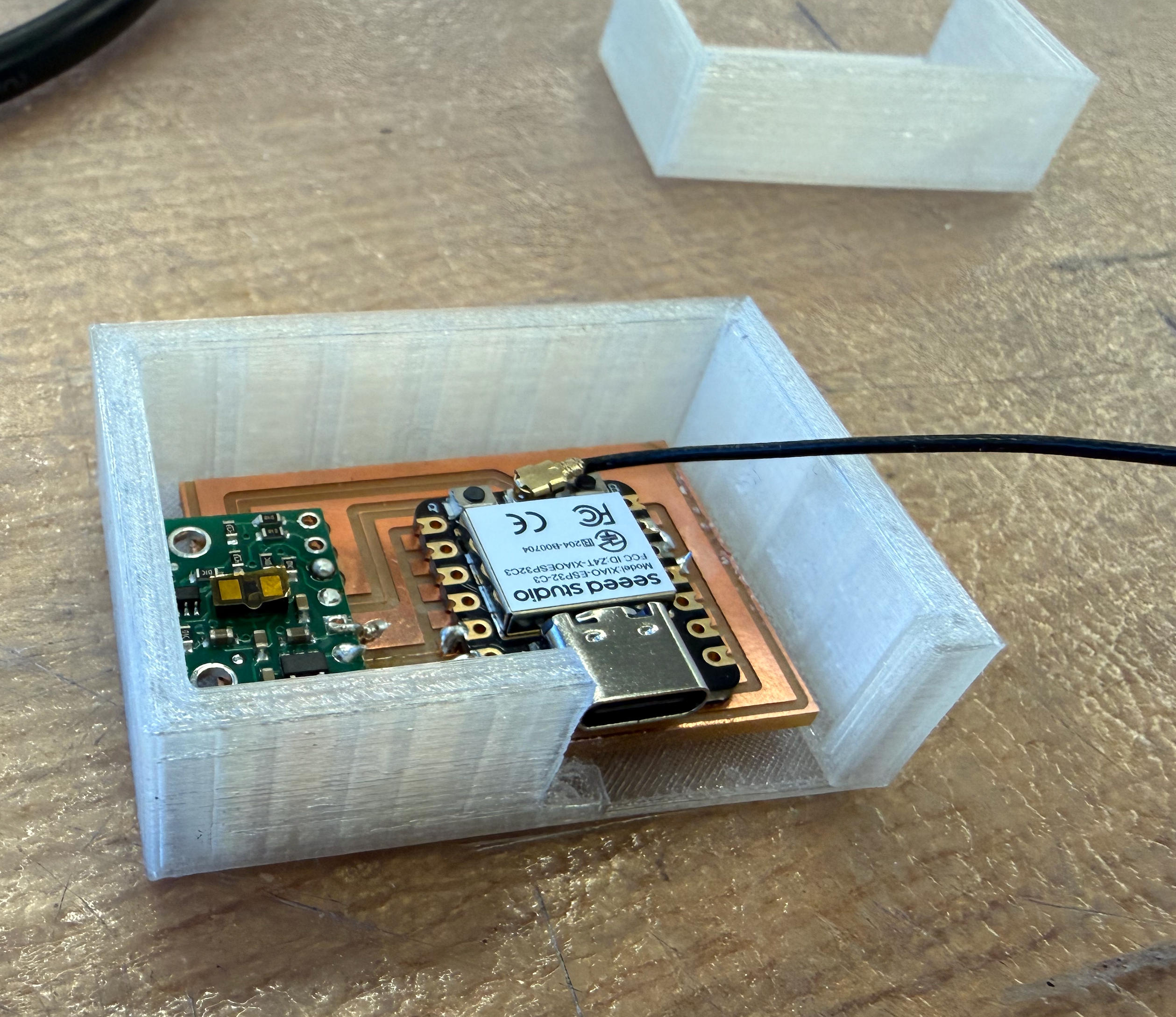
The case is complete and ready for integration
Email Alert System
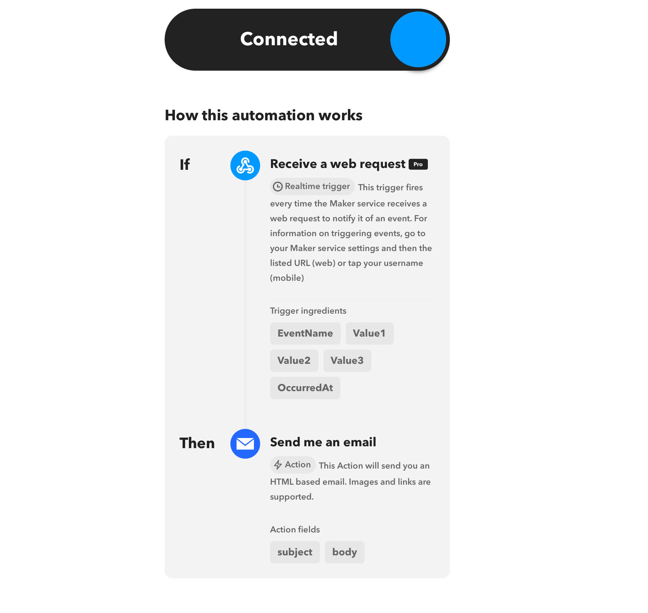
Next onto the email alert system part. Since the microcontroller I'm using, ESP32-S3, has its own wifi module, it is very convenient to implement network features. I googled a bit and decided to implement the email feature via a site called IFTTT.
IFTTT stands for "If this then that." It is a web-based service that allows users to create chains of simple conditional statements, called applets, which are triggered based on changes to other web services such as Gmail, Facebook, Instagram, or Pinterest. In my case, I set up an applet that sends me an email whenever it receives a web request with a specific event name.

Used to send an email to an address I pointed to (in my case, tonyms2023@gmail.com)

Testing and Debugging
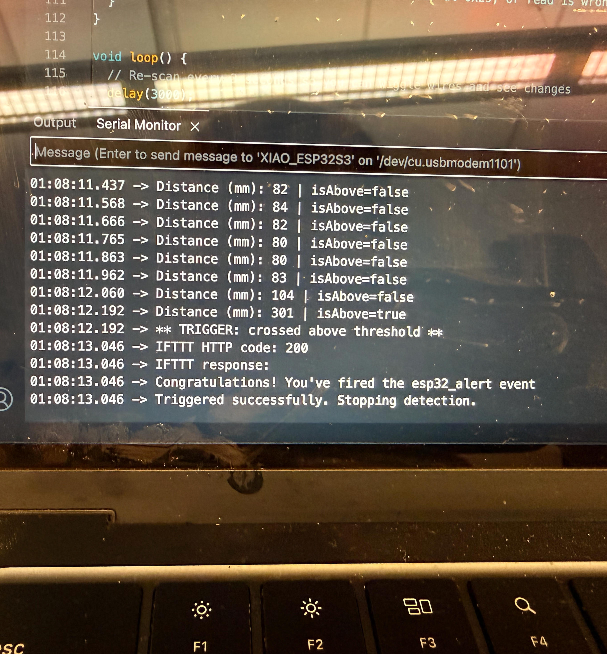
Unfortunately, the board alone worked perfectly when I tested it separately, but once I put it in the case, it stopped working! This was 1:00am in the morning on the day of the demo. My theory is when I pasted the board to the case I accidentally damaged part of the circuit. According to the serial monitor, the networking function works fine, but the program after that cannot be triggered as the distance sensor cannot be found (even though it is obviously still connected).
I tried to find out what went wrong with a multimeter, but no obvious reason was found. To avoid wasting more time on something that I'm not sure I can find quickly, I quickly gathered some new parts and made another one. It is such a good thing I still have the original code that I used for the setup. By the way, I did not know that once the code was uploaded as a sketch, one cannot really retrieve the original code from the microcontroller.
Additional Features and Reflections
One feature I tried and worked in the test but did not work after I tried to implement is the RFID card. I had the idea of using the RFID card I got from Anthony as some kind of remote trigger. By using a card, I don't have to lift the panel every time I want to turn it on or activate it. Ideally it would work when there's something in between. However, it turned out the OSB I used may be too thick for it to work in a stable way. The chance of getting the reader successfully sense the card when there's a board in between is about 50% at any random try. So I abandoned this feature as well.
Arduino Code
#include <WiFi.h>
#include <WiFiClientSecure.h>
#include <HTTPClient.h>
#include <Wire.h>
#include <VL53L1X.h>
// ===================== WIFI + IFTTT =====================
const char* WIFI_SSID = "Tony";
const char* WIFI_PASSWORD = "11111111";
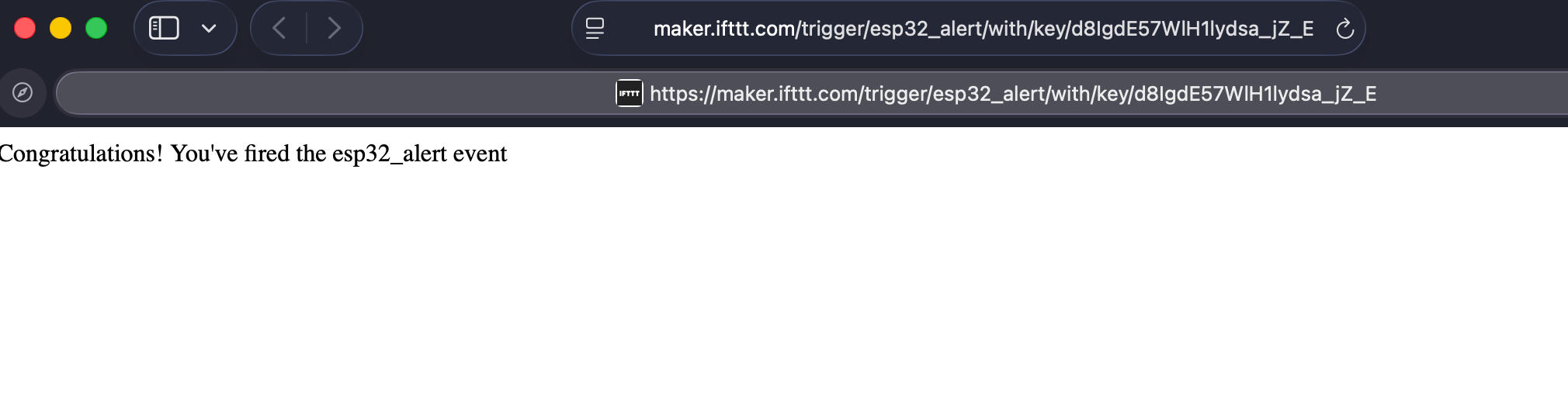
const char* IFTTT_EVENT = "esp32_alert";
const char* IFTTT_KEY = "d8IgdE57WlH1lydsa_jZ_E";
// =======================================================
// ===================== SENSOR / TRIGGER LOGIC ===========
const uint16_t THRESHOLD_MM = 200; // trigger when < 200 mm
const uint16_t REARM_MM = 260; // must rise above this to re-arm
const uint32_t COOLDOWN_MS = 60000; // 1 minute
// =======================================================
VL53L1X sensor;
uint32_t lastTriggerMs = 0;
bool armed = true;
String iftttUrl() {
return "https://maker.ifttt.com/trigger/" + String(IFTTT_EVENT) +
"/with/key/" + String(IFTTT_KEY);
}
bool triggerIFTTT(uint16_t distanceMm) {
WiFiClientSecure client;
client.setInsecure(); // fine for testing
HTTPClient https;
if (!https.begin(client, iftttUrl())) {
Serial.println("HTTPS begin() failed");
return false;
}
https.addHeader("Content-Type", "application/json");
String payload =
String("{") +
"\"value1\":\"ESP32-S3 + VL53L1X\"," +
"\"value2\":\"Distance threshold crossed\"," +
"\"value3\":\"Distance=" + String(distanceMm) + "mm\"" +
"}";
int code = https.POST(payload);
Serial.print("IFTTT HTTP code: ");
Serial.println(code);
Serial.println(https.getString());
https.end();
return (code > 0 && code < 400);
}
void connectWiFi() {
WiFi.mode(WIFI_STA);
WiFi.begin(WIFI_SSID, WIFI_PASSWORD);
Serial.print("Connecting WiFi");
uint32_t start = millis();
while (WiFi.status() != WL_CONNECTED) {
delay(300);
Serial.print(".");
if (millis() - start > 20000) ESP.restart();
}
Serial.println("\nWiFi connected");
}
void setupSensor() {
Wire.begin(); // no explicit pin numbers
delay(50);
sensor.setTimeout(500);
if (!sensor.init()) {
Serial.println("VL53L1X not detected (check wiring & power)");
while (true) delay(1000);
}
sensor.setDistanceMode(VL53L1X::Long);
sensor.setMeasurementTimingBudget(50000);
sensor.startContinuous(50);
Serial.println("VL53L1X initialized");
}
void setup() {
Serial.begin(115200);
delay(300);
connectWiFi();
setupSensor();
Serial.println("Monitoring distance…");
}
void loop() {
uint16_t d = sensor.read();
if (sensor.timeoutOccurred()) {
Serial.println("VL53L1X timeout");
delay(50);
return;
}
Serial.print("Distance (mm): ");
Serial.println(d);
if (!armed && d > REARM_MM) {
armed = true;
Serial.println("Re-armed");
}
uint32_t now = millis();
bool cooldownOk = (now - lastTriggerMs) >= COOLDOWN_MS;
if (armed && cooldownOk && d > 0 && d < THRESHOLD_MM) {
Serial.println("** ALERT: threshold crossed **");
if (triggerIFTTT(d)) {
lastTriggerMs = now;
armed = false;
}
}
delay(100);
}
Power Analysis and Afterthoughts
At the beginning of this project, I had two concerns: whether this thing can work in the dark, and how long a battery-powered device can last given the sustained period of working hours it needs.
Answer for the first question: All the VL53 series distance sensors work perfectly in complete darkness as they use their own active infrared laser emitter (around 940nm). These sensors do not rely on visible light at all; they measure time-of-flight, the timing of the reflected infrared pulse, not brightness. One note is that strong sunlight may interfere with the sensor, but since I'm going to place it in a drawer, in a normal bedroom condition, it should be fine.
For my second concern: Since it needs to constantly emit IR to be working, I was worried it may be very power hungry if I were to power the sensor with just a triple A battery. Based on the information I gathered, I did a bit of math, and here's the answer:
The short answer is: yes, it does have to emit IR regularly, but it can be managed with fine-tuning the frequency. For a single zone sensor (such as VL53L1X), under low rate mode (1 reading/s), average power can drop to 1mW, about 0.3-0.5mA at 3V. Using two AAA batteries to get to 3V and 100mAh capacity, the expected hours can be 1000/20 = 50 hours. This is the most conservative number. I could always switch to a bigger powerbank and lower the frequency even further (say every two hours, because I only need to see if the distance changed at all), and the lasting time would grow exponentially. I'm convinced this could work mathematically.
Based on new parameters, the lasting time could be as long as 10,000 mAh / 0.5 mA = 20,000 hours, approximately 2.3 years (using a 10,000mAh powerbank). This demonstrates how careful power management and optimized sampling rates can dramatically extend battery life for low-power IoT applications.
Project Reflection
| What does it do? | The project is a concealed storage system with an integrated safety and warning mechanism. Although demonstrated inside a drawer, the device functions as a general-purpose motion or proximity detection module capable of triggering alerts when specific conditions are met. |
|---|---|
| Who's done what beforehand? | Prior work included testing distance sensors and fabricating a drawer from OSB using CNC milling. The project builds on earlier HTMAA exercises in digital fabrication, sensing, and embedded programming. |
| What sources did you use? | YouTube tutorials on Fusion 360 and parametric design, HTMAA course materials, and ChatGPT for brainstorming and implementation guidance. |
| What did you design? | I designed the drawer structure, a 3D-printed enclosure for the distance sensor, four internal 3D-printed support structures, the system schematic and PCB, and the embedded software integrating sensing, logic, and Wi-Fi functionality. |
| What materials and components were used? | OSB wood, 3D printing filament, a distance sensor, a custom PCB, an ESP32-S3 microcontroller, and a portable power bank. |
| Where did they come from? | All materials and components were sourced from the lab and HTMAA course inventory. |
| How much did they cost? | The prototype cost was effectively zero. In a real-world deployment, the system would cost approximately $15, primarily for the microcontroller and distance sensor. |
| What parts and systems were made? | CNC-milled drawer components, 3D-printed sensor housing and supports, a custom PCB, and an integrated embedded system with networking capability. |
| What tools and processes were used? | Subtractive fabrication (CNC milling, PCB milling), additive fabrication (3D printing), schematic and PCB design, and embedded programming on the ESP32-S3. |
| What questions were answered? | Sensor durability under battery constraints, physical and detection limitations of distance sensors and RFID readers, and how to implement a complete automation system responding to physical activity. |
| What worked? What didn't? | The main sensing and warning functionality worked reliably. The RFID trigger failed due to excessive material thickness, which reduced the effective detection range. |
| How was it evaluated? | Evaluation was performed through functional testing of sensing accuracy, response reliability, power behavior, and real-world interaction scenarios. |
| What are the implications? | The project demonstrates a low-cost, highly customizable, and rapidly deployable alternative to commercial security systems. While shown in a drawer, the device can be installed in boxes, safes, or behind doors to detect movement and trigger alerts. |